Beam diagrams
To state it explicitly once more, the calculation of internal forces for mechanical systems at rest will be based on:
The necessary and sufficient conditions for static equilibrium of a system,
The fact that any arbitrary part of a system is on itself a new system.
So… what if we chose some of the imaginary boundaries that split our system so that they cut through a body? Let’s consider a system consisting of a single beam 1 and analyze what happens internally to this body.
- 1
A beam will be defined in this context as a long, slender component (i.e. whose length along its main axis is significantly larger than on directions perpendicular to it).
Normal force \(N(x)\)
We reserve the name of normal forces for those who are perpendicular to a given plane of interest. In the context of beams (i.e. slender components), we subdivide a body into subsystems by drawing planes perpendicular to its main axis (x-axis), as shown in the figure below. Normal forces are hence perpendicular to these planes, i.e. parallel to the beam’s main axis.
The first introductory problem to consider will be a 6 meter long horizontal beam resting on two supports:
a roller support at \(x=0\)
a pinned support at \(x=3\text{ m}\)
Show/Hide code for generating the image below
 1beam = Beam(6)
 2beam.rolling_support = 0  # x-coordinate of the rolling support
 3beam.pinned_support = 3    # x-coordinate of the pinned support
 4beam.add_loads([PointLoadH(5, 6)])  # 5 kN pointing right, at x=6 m
 5fig = beam.plot_beam_diagram()
 6ax = fig.gca()
 7ax.text(0, -1.35, r'A', ha='center', va='top')
 8ax.text(3, -1.35, r'B', ha='center', va='top')
 9ax.text(6, -0.5, r'$F_1=5$ kN', ha='right', va='top', color='darkgreen')
10ax.axvline(x=2, linestyle='--', color="k", alpha=0.5)
11ax.text(2, 0.5, r'Section 1-1', rotation=90, ha='right', va='bottom')
12ax.axvline(x=4, linestyle='--', color="k", alpha=0.5)
13ax.text(4, 0.5, r'Section 2-2', rotation=90, ha='right', va='bottom')
14ax.axvline(x=6, linestyle='--', color="k", alpha=0.5)
15ax.text(6, 0.5, r'Section 3-3', rotation=90, ha='right', va='bottom')

The beam is held in place by a rolling support at A and a pinned support at B. A normal (tensile) force \(F_{1} = 5\text{ kN}\) is acting at the right end of the beam.
Let’s find the reaction forces first, so we can proceed with our analysis.
Note
To keep matters simple, the weight of the beam is neglected throughout this analysis.
With the information about the reaction forces at supports A and B, let’s see what happens to the subsystem between the plane 2-2 (located between support B and the right end of the beam) and the plane 3-3 (exactly at the right end of the beam, where the load \(\mathbf{F_1}\) is acting).
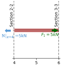
Subsystem between planes 2-2 and 3-3, to the right of support B.
Let’s apply the equilibrium equations to this subsystem. Since we only have colinear forces along the x-axis (we neglect the height of the beam), we write the sum of forces along this direction. The other equilibrium equations are identically zero (no vertical forces or moments acting on the beam), so they don’t add any new information.
Here we have found the internal normal force \(\mathbf{N}\) to be equal to 5 kN. The positive sign corresponds to the standard convention. The normal force \(\mathbf{N}\) is defined as positive when it points outwards. It follows from this that tensile forces are positive and compression forces negative. The result is the same for any plane located between the support B (section 2-2) and the right end of the beam (section 3-3).
Next, let’s consider a slightly different subsystem between planes 1-1 and 3-3 and perform the same analysis
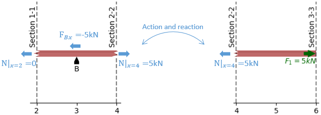
Subsystem between planes 1-1 (btw supports A and B) and 3-3 (beam’s right end)
The normal force \(\mathbf{N}\) across the section 1-1 is zero. Correspondingly, the result is the same for any plane located between supports A (section 1-1) and B (section 3-3).
If we join these last two results, we can reconstruct the normal force \(\mathbf{N}\) along the full beam span as a function of the \(\mathbf{x}\) coordinate, which we will predictably call \(\mathbf{N(x)}\). In this simple case, we end up with the following piecewise function:
Show/Hide code for generating the image below
beam = Beam(6)
beam.rolling_support = 0  # x-coordinate of the rolling support
beam.pinned_support = 3    # x-coordinate of the pinned support
beam.add_loads([PointLoadH(5, 6)])  # 5 kN pointing right, at x=6 m
fig = beam.plot_normal_force()

Shear force \(V(x)\) and moment \(M(x)\)
Let’s do a similar analysis of the same beam for vertical forces. Instead of the horizontal force \(\mathbf{F_1}\), consider now a vertical force \(\mathbf{P_1} = 10\text{ kN}\) acting at the beam’s right end (plane 3-3).
Show/Hide code for generating the image below
 1my_beam = Beam(6)
 2my_beam.rolling_support = 0  # x-coordinate of the rolling support
 3my_beam.pinned_support = 3    # x-coordinate of the pinned support
 4my_beam.add_loads([PointLoadV(10, 6)])  # 10 kN pointing upwards, at x=6 m
 5fig = my_beam.plot_beam_diagram()
 6ax = fig.gca()
 7ax.text(0, -1.35, r'A', ha='center', va='top')
 8ax.text(3, -1.35, r'B', ha='center', va='top')
 9ax.text(5.9, -1.2, r'$P_1=10$ kN', ha='right', va='top', color='darkgreen')
10ax.axvline(x=2, linestyle='--', color="k", alpha=0.5)
11ax.text(2, 0.5, r'Section 1-1', rotation=90, ha='right', va='bottom')
12ax.axvline(x=4, linestyle='--', color="k", alpha=0.5)
13ax.text(4, 0.5, r'Section 2-2', rotation=90, ha='right', va='bottom')
14ax.axvline(x=6, linestyle='--', color="k", alpha=0.5)
15ax.text(6, 0.5, r'Section 3-3', rotation=90, ha='right', va='bottom')

The beam is held in place by a rolling support at A and a pinned support at B. A force \(P_{1} = 10\text{ kN}\) directed upwards is acting at the right end of the beam.
In the same way as before, we start by finding the reaction forces at the supports A and B.
where \(L=6\text{ m}\) is the length of the beam, and \(d=3\text{ m}\) is the distance between supports A and B.
Next, we draw a free body diagram of the beam section comprised between planes 2-2 and 3-3, and do a balance of forces and moments once more.
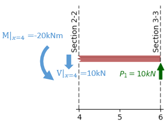
Subsystem between planes 2-2 and 3-3, to the right of support B.
The vertical plane 2-2, corresponds to \(x=4\text{ m}\), hence
\(V|_{2-2} = V(x)|_{x=4\text{ m}} = \underline{10 \text{ kN}}\), and
\(M|_{2-2} = M(x)|_{x=4\text{ m}} = \underline{-20 \text{ kN·m}}\).
The negative value of \(M(x)|_{x=4\text{ m}}\) means that the actual moment acting on the left side of that beam section is opposite to the arrow drawn in the figure above (i.e. clockwise instead of counterclockwise).
Note
The sign convention we follow is shown in the figure below:
A positive normal force N contributes to stretching (elongating) of the beam.
A positive shear force V points upwards (z+) at the right side of the beam (x+), and downwards (z-) at the left side of the beam (x-).
A positive bending moment causes a contributes to stretch on the upper side of the beam and compression on its lower side.
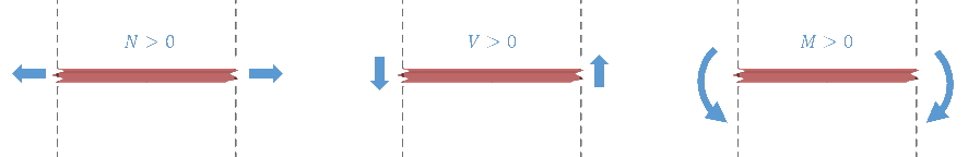
Sign convention used for the beam diagrams: the arrow directions correspond to positive values.
Let’s calculate now the shear force and bending moment at the vertical plane 1-1. To that end, we will consider the beam section between planes 1-1 and 2-2, as shown in the figure below.

Subsystem between planes 1-1 (btw supports A and B) and 3-3 (beam’s right end)
The equations for sum of forces and sum of moments become then:
Tip
This result would (of course) have been the same if our free-body diagram had included the whole beam to the right of the plane 1-1. The same is true for a free-body of the left side of the beam. In order to make sure you will understand the next section, I suggest you stop reading for a moment and try to verify this.
As an exercise, you can follow this procedure and calculate the general result for an arbitrary x-coordinate. You should obtain a function like the one shown in the image below.
Show/Hide code for generating the image below
my_beam = Beam(6)
my_beam.rolling_support = 0  # x-coordinate of the rolling support
my_beam.pinned_support = 3    # x-coordinate of the pinned support
my_beam.add_loads([PointLoadV(10, 6)])  # 10 kN pointing upwards, at x=6 m
fig = plt.figure()
my_beam.plot_shear_force(fig.add_subplot(2, 1, 1))
my_beam.plot_bending_moment(fig.add_subplot(2, 1, 2))
